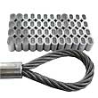
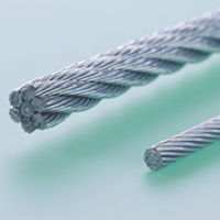
Ferrules / Sleeves
Ferrules are used in numerous applications:
- Construction engineering
- Fishing industry
- Shipyards
- Hoisting industry
- Metallurgy
- Mining
- Conveyor technology
- Petroleum industry
- Medical technology
- Aircraft industry
- Car production
- Marine technology
- Leisure activities
|
|

|

|
|
|
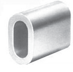
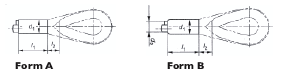
Aluminum EN13411-3 Form A Ferrules
|


|
| Rope
Size IWRC (WC) |
FC(HC) |
Part # |
Sleeve
Size (mm) |
Weight
(lbs) PER 100 pcs |
Packaging
per box |
| 1/32” |
|
RCAL01 |
1 |
0.022 |
1000 |
| 3/64” |
3/64” |
RCAL015 |
1.5 |
0.046 |
1000 |
| 1/16” |
1/16” |
RCAL02 |
2 |
0.066 |
1000 |
| 3/32” |
3/32” |
RCAL025 |
2.5 |
0.110 |
1000 |
|
|
RCAL03 |
3 |
0.185 |
1000 |
| 1/8” |
1/8” |
RCAL035 |
3.5 |
0.290 |
1000 |
|
5/32” |
RCAL04 |
4 |
0.398 |
1000 |
| 5/32” |
|
RCAL045 |
4.5 |
0.574 |
1000 |
|
3/16” |
RCAL05 |
5 |
0.785 |
1000 |
| 7/32” |
7/32” |
RCAL06 |
6 |
1.29 |
1000 |
|
1/4” |
RCAL065 |
6.5 |
1.66 |
1000 |
| 1/4” |
|
RCAL07 |
7 |
2.10 |
1000 |
|
5/16” |
RCAL08 |
8 |
3.01 |
1000 |
| 5/16” |
|
RCAL09 |
9 |
4.36 |
500 |
|
3/8” |
RCAL10 |
10 |
5.81 |
500 |
| 3/8” |
7/16” |
RCAL11 |
11 |
7.88 |
300 |
| 7/16” |
|
RCAL12 |
12 |
10.08 |
200 |
|
1/2” |
RCAL13 |
13 |
13.13 |
200 |
| 1/2” |
9/16” |
RCAL14 |
14 |
16.17 |
200 |
| 9/16” |
5/8” |
RCAL16 |
16 |
24.42 |
100 |
| 5/8” |
|
RCAL18 |
18 |
34.98 |
100 |
|
3/4” |
RCAL20 |
20 |
47.74 |
50 |
| 3/4” |
7/8” |
RCAL22 |
22 |
64.24 |
50 |
| 7/8” |
|
RCAL24 |
24 |
82.72 |
30 |
|
1” |
RCAL26 |
26 |
105.82 |
30 |
| 1” |
1-1/8” |
RCAL28 |
28 |
132.66 |
25 |
|
|
RCAL30 |
30 |
161.48 |
25 |
| 1-1/8” |
1-1/4” |
RCAL32 |
32 |
197.34 |
20 |
|
|
RCAL34 |
34 |
237.6 |
10 |
|
1-3/8” |
RCAL36 |
36 |
280.50 |
10 |
|
1-1/2” |
RCAL38 |
38 |
327.80 |
10 |
|
|
RCAL40 |
40 |
381.48 |
1 |
| 1-1/2” |
|
RCAL42 |
42 |
444.40 |
1 |
|
1-3/4” |
RCAL44 |
44 |
509.08 |
1 |
|
|
RCAL46 |
46 |
562.54 |
1 |
|
1-7/8” |
RCAL48 |
48 |
662.20 |
1 |
|
2” |
RCAL50 |
50 |
748.00 |
1 |
|
|
RCAL52 |
52 |
838.86 |
1 |
|
2-1/8” |
RCAL54 |
54 |
906.40 |
1 |
|
2-1/4” |
RCAL56 |
56 |
1049.84 |
1 |
|
|
RCAL60 |
60 |
1293.60 |
1 |
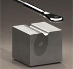
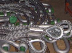
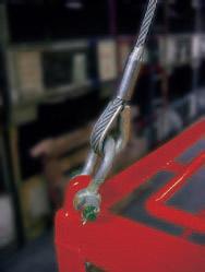
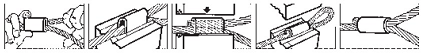
Splicing instructions for Aluminum Ferrules (Form A + B) according to EN 13411-3
|
|
-
Allocation ferrule to wire rope
Select the appropriate ferrule according to our splicing
table. Wire rope constructions with a metallic crosssectional
area factor of less than 0,283 should not be
used. These splicing instructions work for wire rope
constructions according to EN 12385-4. Wire rope
constructions with a tensile grade above 1960 N/mm²
should not be used.
-
Preparation of the rope end
Ensure that the rope remains in lay after cutting and that
no impurities (adhesive tape, etc.) will be within the pressed
ferrule.
-
Selection of swaging dies
Form A should be swaged in approved Universal or
Cylindrical dies. Form B should only be swaged in approved
and specially marked rounded dies. Ensure that the ferrule
code No. and the No. of your swaging die set correspond.
-
Installation and condition of the tooling
Swaging die faces with corresponding numbers need to
be precisely aligned in the die pocket. Dies with worn out
cutting edges do no longer assure an accurate swaging
procedure according to EN 13411-3 and should be
removed from service.
-
Swaging procedure
The procedure shall be carried out by a competent person
trained in ferrule securing. Ferrules 6mm and higher need
to be swaged in hydraulic swagers. Smaller sizes might as
well be swaged with our hand swaging tools.
-
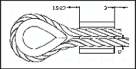
Feed the wire rope through the ferrule in order to provide
the required eye. Return the rope end and form the loop.
If no thimble is fitted, the distance from the ferrule to the
bearing-point should be at least 15 times the rope diameter.
-
The rope diameter D should be the guide value of how far
the dead end of the rope should protrude out of the ferrule
before swaging. This needs to be checked after each swaging
procedure and adjusted if necessary, according to the type
of wire rope, tensile grade and diameter.
-
For satisfactory results you need to first clean and then
lubricate the die bore with mineral grease (no oil) before
each swaging procedure.
-
Place the ferrule centered and ensure that it is truly
vertical within the Die bore.
-
Cease Pressing immediately die faces meet. Do not repress
‘flash’ back into splice.
-
For thimbles without points the gap between the thimble
end and the pressed ferrule should be about 1,5 time the
wire rope diameter D. For thimbles with points the gap
should be 1 time the wire rope diameter D.
-
After swaging the rope ‘dead’end for form A + B should
protrude from the pressed ferrule by up to half a rope
diameter. For ropes that are severed by annealing process,
ensure that the annealed rope portion remains outside the
ferrule after pressing.
-
Ferrules after Swaging
On completion of swaging operation, resultant ‘flash’ must
be removed. Swaging dies in good condition permit to
either break the ‘flash’ off by hand or with a small hammer.
Any residual edge may be filed or otherwise smoothed were
required. Every pressed ferrule needs to be checked for
correct dimensions and position of the ‘dead’ rope end.
The temperature limits when used with a fibre core wire
rope are -40° to +100° C
The temperature limits when used with a steel core wire
rope are -40° to +150° C
-
Marking the ferrule
If the Ferrule secured Eye Termination (FSET) forms part
of a wire rope assembly other than a sling:
-
the ferrule shall be legibly and indelibly marked with the
FSET manufacturer’s name, symbol or mark; and
-
the assembly shall be legibly and durably marked with
the traceability code identifying the assembly with the
certificate in 7.2. of EN 13411-3.
For FSET forming part of a sling you will find further
details in the standard EN 13141-1.
-
Remark
Our ferrule-secured system is in accordance with the type
testing procedure of EN 13411.3 point 5.1.2. for steel wire
ropes defined in EN 12385-4.
Ferrule secured eye terminations should be removed from
service if badly distorted or if body is reduced to 95 % of its
original diameter.
We reserve the right to amend technical data.
 |
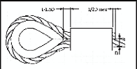 |
| Before Swaging |
After Swaging |
 |
 |
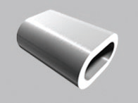
Aluminum EN 13411-3 Form A Oval Ferrules
|
|
|
Rope Ø mm nominal
d |
Rope Ø mm measured |
ferrules according to EURONORM 13411-3 |
|
single layer round strand ropes with fibre core and cable
laid ropes |
single layer round strand ropes with IWRC
and rotation-resistant round strand ropes |
spiral strands (2 ferrules) |
| min. |
max. |
metallic cross sectional area factor C
min. 0,283 |
C up to 0,487 |
C greater 0,487 up to 0,613 |
C min 0,613 |
| 6,5 |
6,5 |
6,9 |
- |
- |
8 |
8 |
| 7 |
7,0 |
7,4 |
- |
8 |
9 |
9 |
| - |
7,5 |
7,9 |
8 |
9 |
9 |
10 |
| 8 |
8,0 |
8,4 |
8 |
9 |
10 |
10 |
| - |
8,5 |
8,9 |
9 |
10 |
10 |
11 |
| 9 |
9,0 |
9,5 |
9 |
10 |
11 |
11 |
| - |
9,6 |
9,9 |
10 |
11 |
11 |
12 |
| 10 |
10,0 |
10,5 |
10 |
11 |
12 |
12 |
| - |
10,6 |
10,9 |
11 |
12 |
12 |
13 |
| 11 |
11,0 |
11,6 |
11 |
12 |
13 |
13 |
| - |
11,7 |
11,9 |
12 |
13 |
13 |
14 |
| 12 |
12,0 |
12,6 |
12 |
13 |
14 |
14 |
| - |
12,7 |
12,9 |
13 |
14 |
14 |
16 |
| 13 |
13,0 |
13,7 |
13 |
14 |
16 |
16 |
| - |
13,8 |
13,9 |
14 |
16 |
16 |
18 |
| 14 |
14,0 |
14,7 |
14 |
16 |
18 |
18 |
| - |
14,8 |
15,9 |
16 |
18 |
18 |
20 |
| 16 |
16,0 |
16,8 |
16 |
18 |
20 |
20 |
| - |
16,9 |
17,9 |
18 |
20 |
20 |
22 |
| 18 |
18,0 |
18,9 |
18 |
20 |
22 |
22 |
| - |
19,0 |
19,9 |
20 |
22 |
22 |
24 |
| 20 |
20,0 |
21,0 |
20 |
22 |
24 |
24 |
| - |
21,1 |
21,9 |
22 |
24 |
24 |
26 |
| 22 |
22,0 |
23,1 |
22 |
24 |
26 |
26 |
| - |
23,2 |
23,9 |
24 |
26 |
26 |
28 |
| 24 |
24,0 |
25,2 |
24 |
26 |
28 |
28 |
| - |
25,3 |
25,9 |
26 |
28 |
28 |
30 |
| 26 |
26,0 |
27,3 |
26 |
28 |
30 |
30 |
| - |
27,4 |
27,9 |
28 |
30 |
30 |
32 |
| 28 |
28,0 |
29,4 |
28 |
30 |
32 |
32 |
| - |
29,5 |
29,9 |
30 |
32 |
32 |
34 |
| 30 |
30,0 |
31,5 |
30 |
32 |
34 |
34 |
| - |
31,6 |
31,9 |
32 |
34 |
34 |
36 |
| 32 |
32,0 |
33,6 |
32 |
34 |
36 |
36 |
| - |
33,7 |
33,9 |
34 |
36 |
36 |
38 |
| 34 |
34,0 |
35,7 |
34 |
36 |
38 |
38 |
| - |
35,8 |
35,9 |
36 |
38 |
38 |
40 |
| 36 |
36,0 |
37,8 |
36 |
38 |
40 |
40 |
| - |
37,9 |
37,9 |
38 |
40 |
40 |
44 |
| 38 |
38,0 |
39,9 |
38 |
40 |
44 |
44 |
| 40 |
40,0 |
42,0 |
40 |
44 |
48 |
48 |
| - |
42,1 |
43,9 |
44 |
48 |
48 |
52 |
| 44 |
44,0 |
46,2 |
44 |
48 |
52 |
52 |
| - |
46,3 |
47,9 |
48 |
52 |
52 |
- |
| 48 |
48,0 |
50,4 |
48 |
52 |
- |
- |
| - |
50,5 |
51,9 |
52 |
- |
- |
- |
| 52 |
52,0 |
54,6 |
52 |
- |
- |
- |
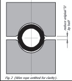
Splicing Instructions for Flemish Eye Sleeves According to EN 13411-3
|
|
-
Allocation ferrule to wire rope
Select the appropriate sleeve according to our
splicing table. Standard Flemish eye carbon steel
sleeves are recommended for use with 6x19,
6x37 or 6x3, IPS or XIP (EIP), XXIP (EEIP)
RRL, FC or IWRC wire rope.
-
Preparation of the rope
Slide the ferrule down the rope.
Un-lay the wire rope. For IWRC rope 3 strands
and core in one group and 3 strands in the other
group.
For FC rope un-lay with 3 strands in each group
and cut away the fibre core.
Cross and lay the one group of strands into
the other group of strands forming a natural
weave. Continue to reweave the group of strands
together to form the eye. The remaining tails
must be as long as the cylindrical part of the
ferrule.
At the end of the eye collect the tails around the
outside of rope dispersing equally and slide the
ferrule over the tails and as far up towards the
eye as possible.
-
Installation and condition of the tooling
Swaging die faces with corresponding numbers
need to be precisely aligned in the die pocket.
-
Swaging procedure
A competent person, trained in ferrule securing
shall carry out the procedure.
Clean and lubricate the bore of the dies with
mineral grease (or high pressure oil) before the
swaging procedure.
Splicing instructions for
Flemish Eye sleeves
according to EN 13411-3
Put the ferrule in the lower half of the cylindrical
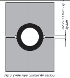
die (STEP 1) and close the dies only so far that
the original gap between the Die faces reduces by
50 % (STEP 2). Open the dies again and turn
the ferrule by 45° to 75°. Re-press again and close
up to ¼ of the original diameter (STEP 3).
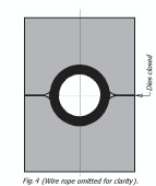
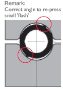
Ensure after STEP 3 procedure that sharp edge
flashing is not occurring, then close the Dies. If
sharp flash is predicted, repeat STEP 3.
Open the dies again and turn the ferrule by 45°
to 75° until the dies can be completely closed
(STEP 4). During these operations there should
not be any pronounced ‘flash’ production.
When using the conical dies it is important to
position splice centrally in Die bore, in order to
permit sleeve elongation in both directions.
Repeat the operations in the same way in the
conical part (set) of dies.
-
Ferrules after swaging
The temperature limits when used with a steel
core wire rope are -60° to +250° C
-
Marking the ferrule
Use round corner stamps to a maximum depth of
0.015” (1/64). The area for stamping should be
on the side of the sleeve in the plane of the sling
eye and no less than 0.250” (1/4) from either end
of the sleeve.
We reserve the right to amend technical data.
 |
 |
 |
 |
 |
| Step 1 |
Step 2 |
Step 3 |
Step 4 |
Remarks |
Standard Flemish Eye Carbon Steel Sleeves
|
|
|
|
|
|
|
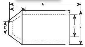
Before swaging dimensions (in.) |
|
| Part # |
Sleeve Size |
Weight per each |
Packing per box |
A |
B |
D |
E |
G |
After Swage dia. |
| BAZ-06 |
1/4" |
5 |
100 |
1.00 |
0.66 |
0.31 |
0.28 |
0.47 |
0.57 |
| BAZ-08 |
5/16" |
14 |
100 |
1.50 |
0.91 |
0.38 |
0.44 |
0.62 |
0.75 |
| BAZ-10 |
3/8" |
14 |
100 |
1.50 |
0.91 |
0.47 |
0.39 |
0.66 |
0.75 |
| BAZ-11 |
7/16" |
33 |
100 |
2.00 |
1.22 |
0.53 |
0.65 |
0.85 |
1.01 |
| BAZ-13 |
1/2" |
29 |
100 |
2.00 |
1.22 |
0.63 |
0.56 |
0.91 |
1.01 |
| BAZ-14 |
9/16" |
64 |
50 |
2.75 |
1.47 |
0.70 |
0.63 |
1.03 |
1.24 |
| BAZ-16 |
5/8" |
56 |
50 |
2.75 |
1.47 |
0.75 |
0.63 |
1.09 |
1.24 |
| BAZ-19 |
3/4" |
88 |
50 |
3.19 |
1.72 |
0.91 |
0.84 |
1.28 |
1.46 |
| BAZ-22 |
7/8" |
131 |
25 |
3.56 |
2.03 |
1.03 |
1.00 |
1.53 |
1.68 |
| BAZ-26 |
1" |
195 |
20 |
4.00 |
2.28 |
1.16 |
1.13 |
1.75 |
1.93 |
| BAZ-28 |
1-1/8" |
260 |
10 |
4.63 |
2.50 |
1.28 |
1.25 |
1.93 |
2.13 |
| BAZ-32 |
1-1/4" |
35 |
10 |
5.19 |
2.78 |
1.44 |
1.41 |
2.16 |
2.32 |
| BAZ-36 |
1-3/8" |
423 |
Bulk |
5.81 |
3.00 |
1.56 |
1.56 |
2.35 |
2.52 |
| BAZ-38 |
1-1/2" |
49 |
Bulk |
6.25 |
3.25 |
1.71 |
1.69 |
2.62 |
2.71 |
| BAZ-45 |
1-3/4" |
805 |
Bulk |
7.25 |
3.84 |
1.94 |
1.97 |
3.13 |
3.10 |
| BAZ-50 |
2" |
1132 |
Bulk |
8.50 |
4.38 |
2.19 |
2.25 |
3.61 |
3.56 |
| BAZ-57 |
2-1/4" |
1934 |
Bulk |
9.56 |
5.03 |
2.50 |
2.53 |
4.03 |
4.12 |
| BAZ-64 |
2-1/2" |
2350 |
Bulk |
10.50 |
5.50 |
2.75 |
2.88 |
4.50 |
4.50 |
| BAZ-70 |
2-3/4" |
2796 |
Bulk |
11.50 |
5.75 |
3.00 |
3.09 |
4.74 |
4.70 |
| BAZ-76 |
3" |
2937 |
Bulk |
12.00 |
6.00 |
3.25 |
3.38 |
5.00 |
4.96 |
| BAZ-89 |
3-1/2" |
463 |
Bulk |
14.00 |
7.00 |
3.88 |
3.94 |
5.84 |
5.77 |
| BAZ-95 |
3-3/4" |
5493 |
Bulk |
15.00 |
7.50 |
4.06 |
4.25 |
6.31 |
6.23 |
|
BAZ-100 |
4" |
6791 |
Bulk |
16.00 |
8.13 |
4.38 |
4.50 |
6.81 |
6.69 |
|
BAZ-115 |
4-1/2" |
998 |
Bulk |
18.00 |
9.13 |
4.88 |
5.06 |
7.66 |
7.45 |
All sleeves are marked for traceability.
For Flemish eye wire rope splicing made with special processed low
carbon steel for better swage ability. Can be stamped for
identification after swaging without concern for cracking with the
following directions. Use round corner stamps to a maximum depth of
0.015 in. (1/64). The area for stamping should be on the side of the
sleeve in the plane of the sling eye, and no less than 0.250 in. (1/4)
from either end of the sleeve. NOTE: Standard Sleeves are recommended
for use with 6 x 19 or 6 x 37, IPS or XIP (EIP), XXIP (EEIP), RRL, FC
or WRC wire rope.
Standard Flemish Eye Carbon Steel Sleeves Specifications
|
|
|
Our carbon steel sleeves are produced with special low carbon
seamless steel, alloyed with the right elements to improve their
mechanical properties and annealed to allow a high degree of
swagability without cracking. For improved corrosion resistance,
sleeves can also be offered galvanized.
All our sleeves are suited for Flemish eye swaging in demanding
rigging, lifting and securing applications.
Our sleeves are independently verified against cracking by accredited
local metallurgical testing laboratories. The sleeves are tested for
composition and compared to others using Energy Dispersive
Spectroscopy and Inductively Coupled Plasma. Sleeves are then
flattened and checked for evidence of no cracking using X-ray
Diffraction.
Mil certificates are available upon request.
|
|
|